
中大、自働化の応用を無限なる可能性を実現する! 詳細 +
-
-
-
製品
詳細
■ 140W □ 104mm
■ Specs / Motor
● This type of motor does not contain a built-in simple brake mechanism.
Model · Type
Lead Wire Type
Rating
Output power
W
Voltage
V
Frequency
Hz
Current
A
Starting
Torque
mN.m
Rated Torque
mN.m
Rated
Speed
r/min
Capacitor
μF
Pinion Shaft
Round Shaft
6RK140GU-AFM
6RK140A-AFM
30min
140
1ph 100
50
2.70
700
1080
1250
35.0
60
3.00
870
1550
6RK140GU-EFM
6RK140A-EFM
30min
140
1ph 110
60
1.80
700
850
1550
25.0
1ph 120
1.95
6RK140GU-CFM
6RK140A-CFM
30min
140
1ph 220
50
1.05
850
1040
1250
10.0
1ph 230
1.15
6RK140GU-HFM
6RK140A-HFM
30min
140
1ph 220
60
1.05
750
850
1550
10.0
1ph 230
1.15
6RK140GU-SM
6RK140A-SM
30min
140
3ph 220
50
0.85
2700
1080
1250
-
60
0.75
2200
870
1550
6RK140GU-S3M
6RK140A-S3M
30min
140
3ph 380
50
0.49
2700
1080
1250
-
60
0.43
2200
870
1550
● When the motor is approved under various safety standards, the model name on the nameplate is the approved model name.
● : Contains a built-in thermal protector(automatic return). If a motor overheats for any reason, the thermal protector is opened and the motor stops.
● When the motor temperature drops, the thermal protector closes and the motor restarts. Be sure to turn the motor off before inspecting.
● Note: "-A" it means the voltage 110V, the assembly capacitor vaule it is according the labe.■ Type
● Motor
Type
Model
Pinion Shaft
Round Shaft
Lead
Wire
Type
6RK140GU-AFM
6RK140A-AFM
6RK140GU-EFM
6RK140A-EFM
6RK140GU-CFM
6RK140A-CFM
6RK140GU-HFM
6RK140A-HFM
6RK140GU-SFM
6RK140A-SFM
6RK140GU-S3FM
6RK140A-S3FM
● Parallel Shaft Gearhead (Sold Separately)
● Enter the gear ratio in the box (□) within the model nameGearhead Type
Gearhead Model
Gear Ratio
Long Life ● Low
Noise
6GU□K
3、3.6、5、6、7.5、9、10、 12.5、15、18、20、25、30、 36、40、50、60、75、90、 100、120、150、180、200
■ Gear Motor-Torque Table
● Gearhead and mid-gearbox can be sold separately. Enter the code that represents the terminal box type (T) in the box (□) within the model name.
● Enter the gear ratio in the box (□) within the model name.
● The colored background indicates the same rotating direction of the motor while the rotating direction of others are opposite.
● The speed is calculated by dividing the motor's synchronous speed (50Hz:1500r/min、60Hz:1800r/min) by the gear ratio. The actual speed is 2%~20% less than the displayed
value, depending on the size of the load.■ Allowance Torque Unit: Upside(N.m)/ Belowside(kgf.cm)
Type
Motor/Gearhead
Gear Ratio
3
3.6
5
6
7.5
9
10
12.5
15
18
20
25
30
36
40
50
60
75
90
100
120
150
180
200
Speed r/min
50Hz
60Hz
500
417
300
250
200
166
150
120
100
83
75
60
50
41
37
30
25
20
16
15
12.5
10
8.3
7.5
6RK140GU-AFM
6RK140GU-CFM
6RK140GU-SFM
6RK140GU-S3FM
6GU□K
50Hz
2.60
3.10
4.40
5.20
6.60
7.90
7.80
9.90
11.8
14.2
14.0
17.8
21.4
25.7
28.0
35.6
40.0
40.0
40.0
40.0
40.0
40.0
40.0
40.0
26.5
31.6
44.8
53.0
67.3
80.6
79.6
101
120
144
143
181
218
262
286
263
400
400
400
400
400
400
400
400
2.50
3.00
4.20
5.10
6.30
7.60
7.20
9.50
11.4
13.7
13.0
17.2
20.6
24.7
26.0
34.3
40.0
40.0
40.0
40.0
40.0
40.0
40.0
40.0
25.5
30.6
42.8
52.0
63.2
77.5
73.6
96.9
116
139
133
175
210
252
265
349
400
400
400
400
400
400
400
400
■ Allowance Torque Unit: Upside(N.m)/ Belowside(kgf.cm)
Type
Motor/Gearhead
Gear Ratio
3
3.6
5
6
7.5
9
10
12.5
15
18
20
25
30
36
40
50
60
75
90
100
120
150
180
200
Speed r/min
50Hz
60Hz
600
500
360
300
240
200
180
144
120
100
90
72
60
50
45
36
30
24
20
18
15
12
10
9
6RK140GU-AFM
6RK140GU-EFM
6RK140GU-HFM
6RK140GU-SFM
6RK140GU-S3FM
6GU□K
50Hz
2.10
2.50
3.50
4.20
5.30
6.30
6.30
7.90
9.50
11.4
11.3
14.4
17.2
20.7
22.6
28.7
34.5
40.0
40.0
40.0
40.0
40.0
40.0
40.0
21.4
25.5
35.7
42.8
54.0
64.2
64.2
80.6
96.9
116
115
147
175
211
231
292
352
400
400
400
400
400
400
400
60Hz
2.10
2.50
3.40
4.10
5.20
6.20
6.10
7.80
9.30
11.2
11.0
14.0
16.8
20.2
22.0
28.0
33.7
40.0
40.0
40.0
40.0
40.0
40.0
40.0
21.4
25.5
34.6
41.8
53.0
63.2
62.2
79.5
94.8
114
112
142
171
206
224
285
343
400
400
400
400
400
400
400
■ To Allow The Hoisting Of The Load Allow Axial Load
Motor (Round shaft) →P215
Gearhead→P215■ Permissible Load Inertia J For Gearhead
P215
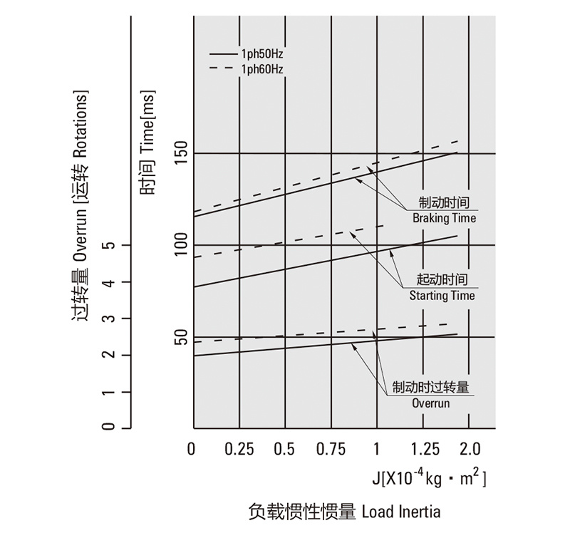
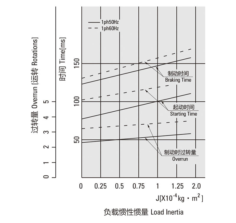
■ Starting And Brake Characteristics (Reference Values)
● Single-phase Motor
 ● Three-phase Motor
■ Dimensions (Unit mm)
Mounting screws are included with gearhead.
● Lead Wiring Type Weight:Motor:5.85kg Gearhead: 2.1kg
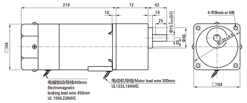
● Enter the gear ratio in the box (□) within the model nameMotor Model
Gearhead Model
Gear Ratio
L1
6RK140GU-AFM
6RK140GU-EFM
6RK140GU-CFM
6RK140GU-HFM
6RK140GU-SFM
6RK140GU-S3FM
6GU□K
3~200
72
● Shaft Section of Round Shaft Type
Excluding weight and the shaft section motor shape are the same as those of the pinion shaft type.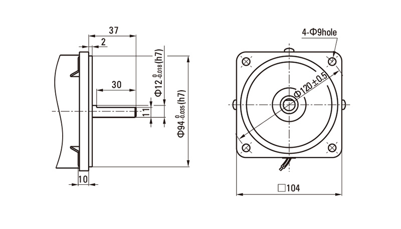
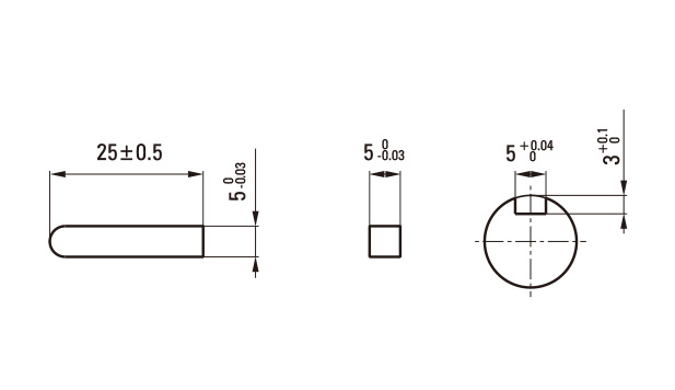
● Key·Keyway (Accessory Of Gearhead)
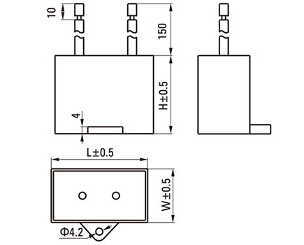
■ Formal Dimension of Capacitor
Note: Conventional capacitor is a lead wire type. Inserted 187# is optionalModel
Capacitor Model
L
W
H
Pinion Shaft
Round Shaft
6RK140GU-AFM
6RK140A-AFM
ZD400CFAUL
58
30
40
6RK140GU-EFM
6RK140A-EFM
ZD300CFAUL
47
27
37
6RK140GU-CFM
6RK140A-CFM
ZD100BFAUL
58
26
38
■ Wiring Diagram
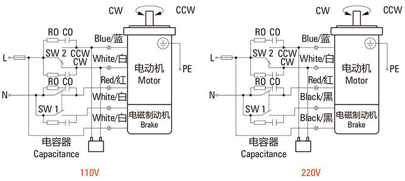
● The direction of motor rotation is as viewed from the shaft end of motor. CW represents the clockwise direction, while CCW represents the counterclockwise direction.
● Name indicated in the list is pinion shaft type, also valid for the equivalent round shaft type.
Single-phase Motor
6RK140GU-AFM、6RK140GU-EFM、6RK140GU-CFM、6RK140GU-HFM
Sw1 operates both motor and electromagnetic brake action. (Switched simultaneously)
The motor will rotate when SW1 is switched simultaneously to ON.
When SW1 is switched simultaneously to OFF, the motor stops immediately with the electromagnetic brake and holds the load.
If you wish to release the brake while the motor is stopped, set the SW1 to off and connection point at the side of black lead to ON.
Direction of Rotation.
To rotate the motor in a clockwise (CW) direction, turn SW2 to CW.
To rotate the motor in a counterclockwise (CCW) direction, turn SW2 to CCW
Switch
No.
Capacitor of Switch Connection Point
Note
Single-Phase 100V,
110/120V Input
Single-Phase 220V,
230V Input
SW1
AC 125V 8A
minimum
(Inductive Load)
AC 250V 8A
minimum
(Inductive Load)
Switched Simultaneously
SW2
-
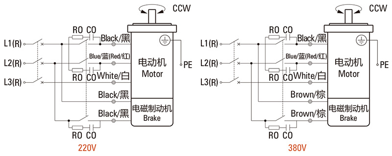
Three-phase Motor
6RK140GU-SFM(S3FM)
SW1 operates both motor and electromagnetic brake action. (Switched Simultaneously)
The motor will rotate when SW1 is switched simultaneously to ON.
When SW1 is switched simultaneously to OFF, the motor stops immediately with the electromagnetic brake and holds the load.
If you wish to release the brake while the motor is stopped, set the SW1 to off and connection point at the side of black lead to ON.
Direction of Rotation.
To change the rotation direction, change any two connections between R, S and T.
.
Switch
No.
Capacitor of Switch Connection Point
Note
SW1
AC 250V 1.5A minimum
(Inductive Load)
Switched
Simultaneously
Notes:
● R0C0 indicate surge suppressor circuit. [R0=5~200Ω, C0=0.1~0.2μF, 200WV (400WV) ] EPCR1201-2 is available as an optional surge suppressor.
関連製品
メッセージ
質問があれば、私達にメッセージを残すことができます。私たちはあなたに返信する専門家を持っています。正しい連絡先情報を入力してください!
寧波中大力徳知能伝動株式有限公司
住所:寧波慈溪高新技術産業開発区新興一路185号
本社電話:+86-4009-002896
北方サービスセンター電話:+86-022-58786102/04
華南サービスセンター電話:+86-769-23606081/82COOKIES
当社の Web サイトでは、お客様に表示される広告をパーソナライズし、お客様が当社の Web サイトで最高のエクスペリエンスを得られるよう、Cookie および同様のテクノロジーを使用しています。 詳細については、プライバシーと Cookie ポリシーをご覧ください。
COOKIES
当社の Web サイトでは、お客様に表示される広告をパーソナライズし、お客様が当社の Web サイトで最高のエクスペリエンスを得られるよう、Cookie および同様のテクノロジーを使用しています。 詳細については、プライバシーと Cookie ポリシーをご覧ください。
これらの Cookie は、支払いなどの基本的な機能に必要です。 標準の Cookie をオフにすることはできず、お客様の情報は一切保存されません。
これらの Cookie は、カスタマー エクスペリエンスを向上させるために、サイトを使用している人の数や人気のあるページなどの情報を収集します。 これらの Cookie をオフにすると、エクスペリエンスを向上させるための情報を収集できなくなります。
これらの Cookie により、Web サイトは拡張機能とパーソナライゼーションを提供できるようになります。 これらは、当社または当社のページにサービスを追加したサードパーティプロバイダーによって設定される場合があります。 これらの Cookie を許可しない場合、これらのサービスの一部またはすべてが正しく機能しなくなる可能性があります。
これらの Cookie は、お客様が何に興味を持っているかを理解するのに役立ち、他の Web サイトで関連する広告を表示できるようになります。 これらの Cookie をオフにすると、パーソナライズされた広告を表示できなくなります。
-


